
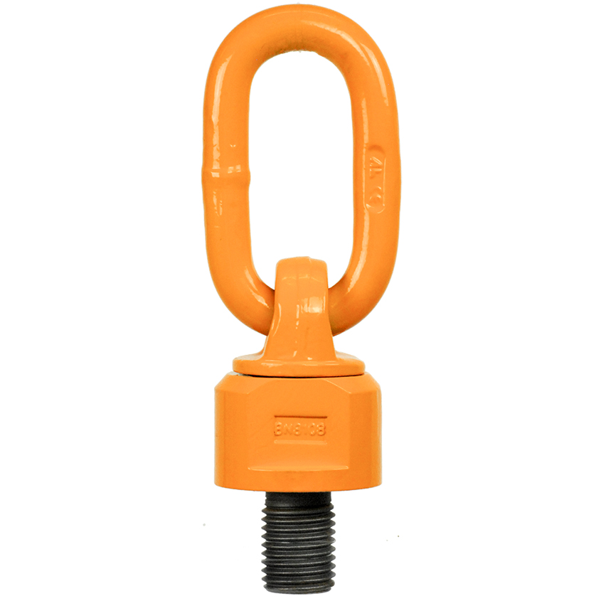
Oblong Eye Bolt – Swivel Eye Bolts G80 Series
Design
- Low carbon alloy material.
- Large eye size for utilised applications.
- Integrated ball bearing for swivelling under load.
- Marked with WLL, bolt size, batch and Austlift or AL.
Testing
- Proof tested at 2.5 x WLL with ball bearing installed.
- Destructive tested at 4 x WLL with ball bearing installed.
- All tested at 45 degree angles off axle line.
- Fatigue tested at 1.5x WLL, minimum 20000 time, in axle direction.
- Low temperature and cryogenic tested, at -20°C, minimum 25J.
- Magnetic crack tested on each eyebolt.
- Visual tested after assembled.
- Testing certificates available upon request.
Manufacturing
- Forged.
- Heat treated.
- Powder coated finishing.
Swivel ring bolt accordingly to EN 818-4 for load ring and AS2318 for the swivel component. Used as a swivelling load ring capable of rotating under load due to ball bearing rings ideally suited for dynamic lifting in any position.
- Made from G80 alloy steel with orange painted finish, manufactured with an oval link, and available in metric thread sizes from 8mm to 36mm.
- Marked with working load limit in tonne, nominal size in millimetre, quality mark and supplier identification. Proof tested to 1.25 x Working load limit.
- Test certificates are available upon request.
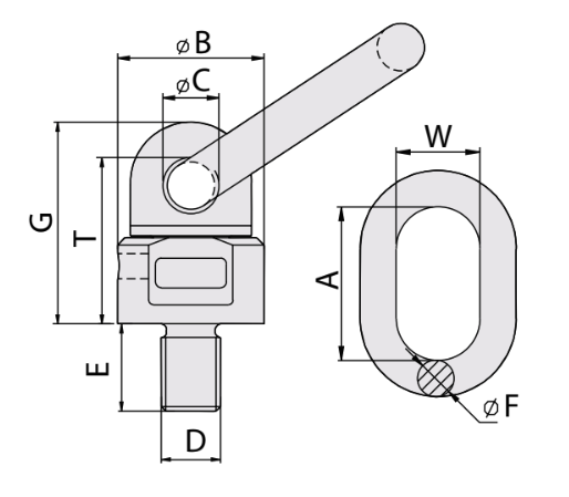
| CODE | SIZE (mm) | PITCH (mm) | WLL (T) | Wt. (kg) | DIMENSIONS (mm) | ||||||||
|---|---|---|---|---|---|---|---|---|---|---|---|---|---|
| 0° | 90° | A | B | C | E | F | G | W | T | ||||
| 605108 | 8 | 1.25 | 0.6 | 0.3 | 0.41 | 55 | 36 | 15 | 13 | 13 | 51 | 30 | 41 |
| 605110 | 10 | 1.50 | 0.9 | 0.45 | 0.43 | 55 | 36 | 15 | 18 | 13 | 51 | 30 | 41 |
| 605112 | 12 | 1.75 | 1.0 | 0.5 | 0.44 | 55 | 36 | 15 | 18 | 13 | 51 | 30 | 41 |
| 605116 | 16 | 2.00 | 2.0 | 1.12 | 0.46 | 55 | 36 | 15 | 20 | 13 | 52 | 30 | 42 |
| 605120 | 20 | 2.50 | 4.0 | 2.0 | 0.96 | 70 | 49.5 | 19 | 30 | 16 | 68 | 35 | 56 |
| 605124 | 24 | 3.00 | 6.3 | 3.15 | 1.45 | 85 | 57 | 22 | 30 | 18 | 78 | 40 | 65.5 |
| 605130 | 30 | 3.50 | 10.6 | 5.3 | 2.17 | 85 | 66 | 23.5 | 35 | 20 | 96.5 | 40 | 80.5 |
| 605136 | 36 | 4.00 | 11.8 | 8.0 | 3.6 | 115 | 80 | 27 | 50 | 22 | 109 | 50 | 89.5 |
Warning
- Swivel ring bolts should be tightened by spanner with torque wrench.
- These ring bolts are not designed for permanent rotating continuously.
- Not suitable for turning under full load at 90° in side loading position.
| METRIC | WORKING LOAD LIMIT FOR OBLONG EYE BOLT | ||||||||
|---|---|---|---|---|---|---|---|---|---|
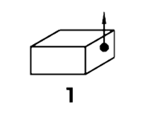
| LOADING METHOD | 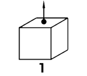 |
 |
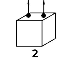 |
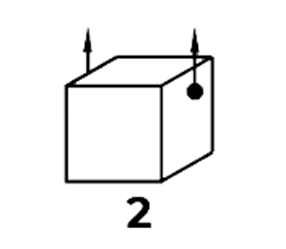 |
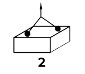 |
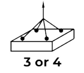 |
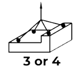 |
||
| INCLINATION | 0° | 90° | 0° | 90° | SYMMETRIC | ASYMMETRIC | |||
| 0°-45° | 45°-60° | 0°-45° | 45°-60° | ||||||
| LOAD FACTOR | 2.0 | 1.0 | 4.0 | 2.0 | 1.4 | 1.0 | 2.1 | 1.5 | 1.0 |
| M8 | 0.6 | 0.3 | 1.2 | 0.6 | 0.42 | 0.3 | 0.63 | 0.45 | 0.3 |
| M10 | 1.0 | 0.5 | 2.0 | 1.0 | 0.7 | 0.5 | 1.05 | 0.75 | 0.5 |
| M12 | 1.0 | 0.5 | 2.0 | 1.0 | 0.7 | 0.5 | 1.05 | 0.75 | 0.5 |
| M16 | 2.24 | 1.12 | 4.48 | 2.24 | 1.57 | 1.12 | 2.35 | 1.68 | 1.12 |
| M20 | 4.0 | 2.0 | 8.0 | 4.0 | 2.8 | 2.0 | 4.2 | 3.0 | 2.0 |
| M24 | 6.3 | 3.15 | 12.6 | 6.3 | 4.41 | 3.15 | 6.62 | 4.73 | 3.15 |
| M30 | 10.6 | 5.3 | 21.2 | 10.6 | 7.42 | 5.3 | 11.13 | 7.95 | 5.3 |
| LOAD FACTOR | 1.6 | 1.0 | 3.2 | 2.0 | 1.4 | 1.0 | 2.1 | 1.5 | 1.0 |
| M36 | 12.8 | 8.0 | 25.6 | 16.0 | 11.2 | 8.0 | 16.8 | 12.0 | 8.0 |